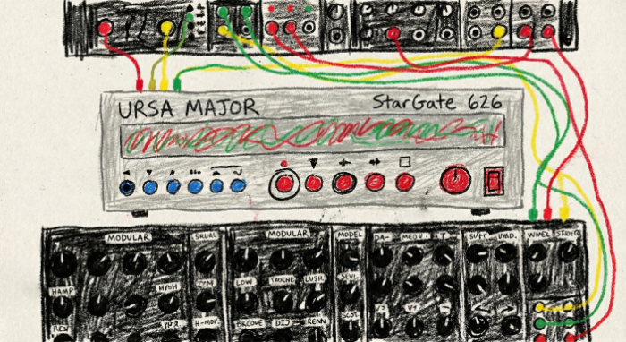
Anatomy of the StarGate 626: A PROM-Driven Reverb
January 28, 2026
Modern reverbs run on DSP chips executing arithmetic in tight loops. The StarGate 626 does not. Its algorithm lives completely in burned EPROM lookup tables, orchestrated by TTL counters and latches clocked at 8.192 MHz. There's no multiply-accumulate unit, no floating-point math, or any code. The circuit counts, looks up, and latches. 256 steps per cycle, 32,000 cycles per second.
The Timing System
A crystal oscillator running at 8.192 MHz drives the system. Two chained 74LS163 counters divide that clock into an 8-bit master count that cycles from 0 to 255. That count is the address input to two timing PROMs, each a 256-byte lookup table that outputs a different control word at each step. Three 74LS374 latches capture those outputs and distribute them across the circuit as stable control signals: RAS and CAS for memory access, DAC enable, modulation enable, synchronous clear.
The 256-step cycle repeats 32,000 times per second. Every other subsystem (delay addressing, modulation, gain shaping) is slaved to signals derived from this counter. The designers didn't build state machines or use conditional logic. They pre-computed the exact sequence of control signals they wanted and burned it into two PROMs. The circuit just counts and reads.
TCB1 pulses 64 times per cycle, and each pulse advances a slot counter that addresses the delay tap memory. TCB1 is the bridge between the timing system and the delay line—without it, nothing moves.
The 8.192 MHz crystal drives a master counter (TC0–TC7) through 256 steps. Timing PROMs decode each step into control signals, including TCB1, which fires 64 times per cycle to advance the DAC slot counter (TCB2–TCB7). Every 16 steps, the lower address nibble rolls over. TCB7, the slot counter's MSB, transitions twice per cycle — its rising edge clocks both the write address counter and the modulation rate counter.
The Delay Taps
TCB1 drives a 6-bit DAC slot counter that addresses 64 tap positions per cycle. Each tap's delay time comes from a 16K EPROM indexed by three things: the slot number, the pre-delay knob setting, and the selected program. Different programs store different tap patterns, each with its own reverb character, in the same EPROM, selected by the front-panel switch.
But the delay EPROM doesn't feed the memory address bus directly. Its output passes through an adder stage that combines it with the current write address, and then through a bit permutation that rearranges the result. The shuffle pattern takes bits 0 through 7 and reorders them to 6, 0, 1, 2, 3, 4, 5, 7. Without the shuffle, taps that are numerically close in the EPROM would land at adjacent memory addresses, producing a comb-filtered, metallic sound. The permutation scatters them across non-contiguous memory locations, decorrelating the taps and breaking up the regularity that makes cheap delay lines sound cheap.
The result is a set of delay taps whose positions are defined entirely by the data burned into the EPROM. Changing the tap pattern (the density, spacing, and distribution of early reflections versus late diffusion) means changing the data, not the circuit.
The delay adder's output bits are physically wired in a rotated order: bits 0–6 shift up by one position, and bit 6 wraps to position 0. Bit 7 stays put. The grids below show 256 memory locations. As values are written sequentially (left), the shuffle scatters their read-back addresses across the memory space (right), decorrelating adjacent taps.
Modulation
A static set of delay taps produces a static reverb. To add movement, the StarGate 626 has a second delay EPROM that provides time-varying tap positions. The circuit alternates between the static and modulated EPROMs on a per-slot basis using the MOD_bar timing signal. Some taps get their positions from the fixed table; others get theirs from the modulated table. Each cycle, the modulated taps are in slightly different places.
There isn't a rate knob. Modulation speed comes straight from the input signal. An envelope follower built around a bandpass filter (106–370 Hz) and rectifier tracks the input level with a fast 1ms attack and slower 100ms release. The envelope value is quantized into one of five discrete rate levels by a set of thresholds, and that level indexes a rate PROM to select a counter preload value. The preloaded counter divides the master clock down to a modulation clock (MCCK), which drives a 13-bit free-running counter. That's 8,192 steps before it wraps. Louder input means faster modulation. As the signal decays, the modulation slows with it.
This is a different approach from the wavetable LFOs found in most modern effects. There's no stored sine or triangle wave driving a delay offset. Instead, the modulation shape is implicit in the EPROM data itself. Each value of the 13-bit counter pulls a different row from the lookup table, and the pattern of those rows over time defines the modulation waveform. The shape can be anything the designer burned in: sinusoidal, stepped, asymmetric, or something that has no simple mathematical description.
Delay offset waveforms for six taps over one full modulation cycle (128 phases). Each line shows how a single tap's delay position shifts over time. The staircase shape — roughly 10 discrete steps per cycle — reflects the quantized nature of the lookup tables. These aren't mathematical functions. Ursa Major designed them this way and tuned them by hand.
The Gain Waveform
Every tap also carries its own gain level, controlling how loud it sits in the mix. That gain curve is really what defines the reverb's decay. Early reflections hit harder, late diffusion drops off, and the shape of that rolloff determines whether the tail sounds natural or synthetic.
The gain path runs through two cascaded EPROMs. The first one (U78) defines the base decay envelope. Its address combines the DAC slot number, the decay knob setting, and the program selection, so each program can have a completely different decay shape, and the decay knob scales it. The output is a 6-bit gain value per tap.
The second EPROM (U77) modulates that envelope over time. Its address includes the output of the first EPROM plus bits from the modulation counter. This means the gain isn't static—it shifts with the modulation phase. Taps breathe. The decay envelope isn't a fixed curve, it's a surface that evolves across both tap position and time. All from two lookup tables, no arithmetic.
The Gain Ceiling
The modulated gain path can produce spikes, moments where the combination of base envelope and modulation phase pushes a tap's gain higher than intended. Left unchecked, these spikes would cause the reverb tail to pop and crackle.
The StarGate 626 handles this with a hardware limiter built from two 74LS85 magnitude comparators and a NAND gate. The comparators take the modulated gain value on one side and a fixed gain reference on the other. They output which is larger, and the NAND gate selects the minimum of the two. If the modulated gain is below the reference, it passes through. If it exceeds the reference, the reference value is used instead.
This is a hard ceiling, not a soft knee compressor. The gain hits it and stops. It keeps the reverb tail smooth and prevents the modulation from introducing artifacts.
The modulated gain signal (dim) pushes above the ceiling threshold (dashed red). Two 74LS85 comparators select the minimum of the modulated gain and the fixed reference — everything above the ceiling is flattened. The bright line shows what passes through.
The Algorithm Is the Data
In a modern plugin, the algorithm is code: feedback delay networks, allpass filters, diffusion matrices. In the StarGate 626, the algorithm is data. Six EPROMs totaling 56 kilobytes define everything: the timing sequence, the tap positions, the modulation shapes, the decay curves. The circuit itself is generic plumbing: counters, latches, adders, comparators. Swap the EPROMs and you have a different reverb. There are no feedback loops except the intentional modulation path, no state beyond the counters. Given the same EPROM contents, it produces exactly the same output every time.
© 2026 Temecula DSP.
SST-282, SST-206 and Stargate 626 are model numbers originally used by Ursa Major and Seven Woods Audio. Temecula DSP is not affiliated with the estate of Christopher Moore, Ursa Major, or Seven Woods Audio.
DP/4 is a trademark of Creative Technology Ltd. Temecula DSP is not affiliated with, endorsed by, or sponsored by Creative Technology Ltd.
"Alesis" and "MidiVerb" are trademarks of inMusic Brands, Inc. Temecula DSP is not affiliated with, endorsed by, or sponsored by inMusic Brands, Inc.