What Makes the Space Station Different
January 30, 2026
Modern reverbs use allpass filters and diffusion matrices to feed a delay line's output back into its input. In 1978, those techniques hadn't been developed yet for real-time digital hardware. The Ursa Major Space Station took a different approach, splitting the problem in two: one set of taps for listening, a completely separate set for feedback. The taps you hear never recirculate, and the taps that recirculate are never heard directly. This separation is the core of the Space Station's architecture, and it's what makes it sound the way it does.
One Buffer, Two Systems
Everything starts with a single circular delay buffer where audio goes in and the write head advances continuously. Reading back from that buffer at different points in time gives you delayed copies of the input. Most delay-based effects work this way.
What's unusual with the Space Station is how it reads from that buffer. Two independent systems pull audio out of the same memory, for completely different purposes.
The first system is the audition taps: eight fixed-position taps that create the stereo output you actually hear. Odd-numbered taps go to the left channel, even-numbered taps go to the right. Four knobs control their levels in pairs: taps 1 & 2, 3 & 4, 5 & 6, 7 & 8. The delay times for these taps are defined by the selected delay pattern, one of 16 programs with names like Room 1, Comb 6, Fatty, Cloud, Slap 1, Echo, and Space Repeats.
The second system is the feedback taps: fifteen modulated taps whose outputs are summed, filtered, and fed back into the buffer input. You never hear these taps directly. Their job is to build up echo density over time, creating the reverberant tail that gives the Space Station its eerie, otherworldly character. The audition taps then let you listen to the result.
Play the samples above to hear the beautiful, ghostly reverb tail of the superlative Space Station.
Why Separate Them?
Modulating the feedback taps is essential for stability. Without it, the recirculating signal quickly develops a metallic, comb-filtered sound, or worse, can oscillate into instability. But modulation introduces artifacts: small amplitude skips at each time step, and Doppler-like pitch shifting as the tap positions move. If you listened to modulated taps directly, you'd hear noise and pitch wobble on everything, including the original dry signal sitting in the buffer.
By separating the two systems, the audition taps read from fixed positions. The original signal comes through clean. The fed-back portion of the sound in memory carries the modulation artifacts, but those artifacts are buried under layers of recirculation. They become part of the texture rather than a flaw. It's an elegant trade-off that lets the Space Station use aggressive modulation for stability without paying the price in output quality.
The Audition Tap Patterns
The eight audition taps are arranged into 16 programs across four families. The Room patterns (1 through 4) use semi-random delay spacings that mimic early reflections in progressively larger spaces, from about 70ms maximum delay in Room 1 up to 255ms in Room 4. The Comb patterns space their taps at constant intervals to create precise spectral notches and peaks. Fatty and Cloud cluster all eight taps within the first 30–60ms, below the Haas fusion threshold, where they aren't heard as separate echoes but instead add perceived loudness and width. The Space Repeats use carefully paired timing differentials between left and right taps to create spatial bouncing via the Haas effect.
What matters is that switching between these patterns changes only where the audition taps read from the buffer. The feedback system, the part that generates the reverberant tail, doesn't change at all. You can audition the same reverberant field through completely different temporal lenses: hear it as a room, hear it as a comb filter, hear it as a slap echo. The listening window and the reverb engine are independent.
Signal flow through the Space Station reverb. Audio enters the input mixer, which combines dry signal with the feedback return. Two independent tap systems read from the same delay buffer: fixed taps create the stereo output, modulated taps feed back into the input. Click to pause.
The Feedback Taps and Their Modulation
The fifteen feedback taps are arranged as seven complementary pairs plus one unpaired tap. Each pair shares the same triangle-wave LFO depth (plus or minus 4ms) but runs in opposite phase. When one tap's delay time is increasing, its partner's is decreasing. This cancels the net Doppler shift. Without it, the summed feedback signal would wander in pitch as the majority of taps moved in the same direction.
The LFO periods increase with the base delay time, from 1.5 seconds for the shortest taps to 8.2 seconds for the longest. Shorter taps get faster modulation because they're more prone to producing audible repeating patterns, so they need more aggressive randomization. Longer taps take more time to reveal a repeating pattern, so they can be modulated more slowly, and slower modulation means less noise and pitch distortion.
The base delay times themselves are spaced with decreasing increments as the delays get longer. The shortest tap sits at 47ms, the longest at 247ms, and the gaps between them narrow from 73ms down to 3ms. This packs more taps into the longer delay range, which builds echo density over time, mimicking how reflections multiply in a real room.
STANDARD TAPE ECHO
FIXED TAPS
TEMECULA DSP SST-206
MODULATED TAPS
What You're Actually Hearing
When you turn the decay time knob, you're controlling the gain of the feedback path. At zero, the feedback taps are silent and the audition taps give you pure delay: eight copies of the input at specific time offsets. As you increase it, the feedback taps start recirculating, building up a reverberant field inside the buffer. The audition taps give you a window into that field.
The equalization controls (LF Decay and HF Decay) sit inside the feedback loop. Each recirculation pass gets re-filtered, so high frequencies accumulate more loss per pass than low frequencies, or vice versa. This is how you shape the decay character, not by changing the tap positions, but by shaping what survives each pass through the loop.
A Different Kind of Reverb
The Space Station's two-tap architecture is fundamentally different from the feedback delay networks and allpass chains that dominate modern reverb design. There's no diffusion matrix, no Hadamard transform, no lattice structure. There's a buffer, two independent tap systems, and a feedback path with filtering and modulation. The reverb character comes from the tap positions (burned into PROMs in the original hardware), the modulation scheme, and the feedback path constraints. Change any one of those and you get a different reverb. But the architecture, the separation of listening from feedback, stays the same.
That separation is what gives the Space Station its particular combination of clarity and density. The direct signal and early reflections arrive clean through fixed taps. The reverberant tail builds through a separate, heavily modulated feedback path. You hear both simultaneously, but they're generated by independent systems reading from shared memory. It's an idea from 1978 that still sounds like nothing else.
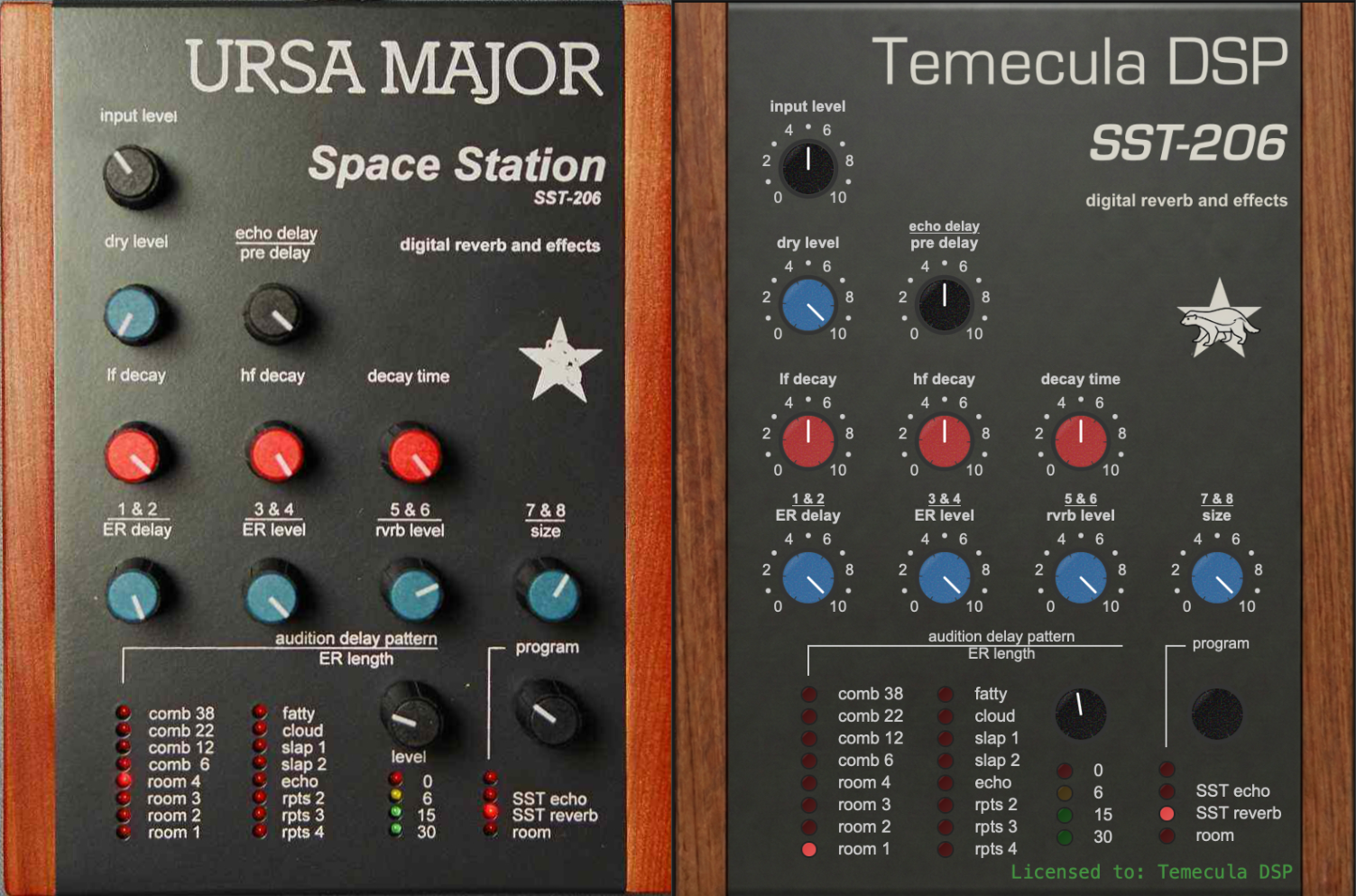
They may look a little different on the outside, but their insides produce identical sounds.
© 2026 Temecula DSP.
SST-282, SST-206 and Stargate 626 are model numbers originally used by Ursa Major and Seven Woods Audio. Temecula DSP is not affiliated with the estate of Christopher Moore, Ursa Major, or Seven Woods Audio.
DP/4 is a trademark of Creative Technology Ltd. Temecula DSP is not affiliated with, endorsed by, or sponsored by Creative Technology Ltd.
"Alesis" and "MidiVerb" are trademarks of inMusic Brands, Inc. Temecula DSP is not affiliated with, endorsed by, or sponsored by inMusic Brands, Inc.